I have already been using Processing and am excited to take projects beyond the computer. So the point of Arduino is that the microprocessor facilitates interaction with the environment including human interfaces beyond the screen, keyboard and mouse. Inputs can be considered environmental sensors that measure things like sound, light, heat, movement. A very cute example is Rob Faludi's Botanicalls that measures soil moisture and sends tweets to remind you to water your plants and then once you have sends another tweet thanking you.
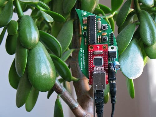 |
| Botanicalls, Rob Faludi and SparkFun |
We started with a tutorial by Lady Ada to upload code to the microprocessor that caused a LED to blink. This apparently is the hardware equivalent of a hello world.
 |
| Arduino microprocessor with simple circuit (blinking LED) |
The colour of cables is used to organise the circuit with clarity - we are using black for ground and red for high voltage (apparently these are conventions), and then green and orange for variable signals as input and output respectively.
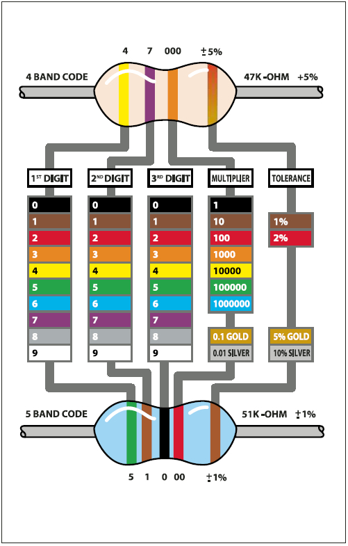
Resistors are important to restrict the current, both to ensure that fragile parts such as the diode dont get fried and to reduce the risk of electrocution. I am not yet totally across when to use resistors and how much resistance to choose - I suppose it always somewhat necessary to check specification of parts. Lady Ada suggests that a 100 ohm resistor is sufficient to protect a diode and that generally a 1000 ohm (1K ohm) resistor is a good place to start. The relationship between current, resistance, and voltage is described by Ohm's Law: Current (I) = Voltage (V) / Resistance (R). The level of resistance is notated with coloured bands.
The way we controlled the blink is with simple code that in the loop function (equivalent to the draw function in Processing) says light on (high voltage signal), then delay (pause the program, light remains on), light off (low voltage signal) and then delay again (pause the program, light remains off).
We also learnt about drawing circuit diagrams, as you can see in the background of the above picture.
The next project was to reconfigure the circuit to make the LED dim-able. We added a flex sensor as an input - it is a variable resistor that changes input signal (voltage drop) as it is bent. The input and output signal had to be connected to an analog pin on the Arduino microprocessor. The analog pins (marked ~ ) can use pulse width modulation (PWM) to vary voltage - how this actually works is that the duty cycle or the amount of time that is high or low each clock cycle can be set between 0 (always low) and 255 for output or 1023 for input (always high) effectively turning on/off so quickly that it is imperceptible and appears as continuous and smooth. As there are different ranges for the input and output values it is necessary to calibrate - in this case we offset the input value to be below 255.
 |
| LED dimmed using flex sensor as input |
No comments:
Post a Comment