Saturday, April 30, 2011

D, I & E Intensive 2 Day 3

We now have the projects substantially finished, but we didnt get to install them today or test how they interact or give them individualised behaviours. We will get together for another workshop in the holidays and do a test install then before the exhibition at the Belconnen Arts Centre. I suppose that is an important lesson in just how long all the little things take to get done, and how often things dont work smoothly as expected and so need resourceful on the spot thinking.

I do feel like I have come a long way in 6 days, and have confidence now to finish my tile myself - and then go on to do any other project on my own. I had never worked with electronics before this.

SOFTWARE

I wrote my first library! What a challenge - after spending the evening before adapting our code to classes as I would set them up in Processing, I spent almost the entire morning figuring out how to make them work in Arduino as a library.
Code with library header and class files in foreground
Essentially Arduino is built on C++, which has similar syntax to Processing which is built on Java - but they are not the same or directly compatible. I will have to read up more about this. The previously linked to tutorial was very helpful and got the basic setup for me.

However after hours of debugging and browsing the Arduino forums I still had one unsolvable problem - I couldn't get the constructor to recognise instances of custom classes. I had made seperate led and light sensor eye classes, and was trying to get the led class to know about their own eye as well as the other 3 eyes in the tile. So I got around this by unifying the classes in a single cell class. Lesson - try to make two classes talk to each other at your own peril!

There are a few other key differences between this and a Processing implementation:
  1. the code is written in separate files that are saved in the libraries directory of the Arduino install directory (Arduino/libraries) and edited in a text editor such as notepad, these are:
    1. Cell.cpp, the class file where all the code goes
    2. Cell.h, a header file which is like a contents
    3. keywords.txt, a list of keywords to highlight the code in Arduino
  2. there is additional wrapping syntax before the constructor and other functions in the class file (ie Cell : : )
  3. there must be a link to the standard Arduino library (ie #include "WProgram.h" ) and any other libraries you are using (if you can get them to interface!)
  4. the header file lists the constructor and all the parameters and functions, so is a handy reference to remember the names you can call - public functions and parameters can be called, manipulated, updated etc in the same way as you would with Processing classes - private functions and parameters can only be called from within the class
  5. in your Arduino code you need to import the library (ie #include <Cell.h> ) and remember to restart Arduino to get it to recognise a new library
It should be easy to hack the library as the code resembles Processing - just remember to add new parameters and functions to the header file. Perhaps adding a timer to keep track of the time that the light has been off would be useful.

However I have tried to design the library to be flexibile so that for most of the things we might want to achieve with the tiles we shouldnt have to touch it. There are some global variables that can be updated via the cellSettings() function. I have added parameters to control the eye flag threshold for turning on/off the LEDs, change the delay between the eye flags and the LEDs turning on, and to set a minimum time that the LEDs have to be on before they can be turned off. I have also added a boolean switch to turn on/off the fade and a time step to lengthen the time it takes to fade.

There is lots that can be done from outside the library - for example the knob is hooked up to change the flag delay via the cellSettings() function and the buzzer is set up with all of it's parameters (frequency, duration etc) outside the library and is hooked up to make a tone when it recieves a toneSet signal which is sent when a cell turns on the lights in the function doLight(). The pressure sensor controls lights differently, outside of the library ( ie not in doLight() ), by simply setting brightVal to be 255. The LEDs can be set at anytime to be any gradient of brightness by changing brightVal.

Also I gave each of the cells specific names (topLeftCell, bottomRightCell etc) not because it matters which way the tile is oriented, but so that it would be easy to program communication between cells remembering which cell is clockwise or anticlockwise adjacent or diagonally opposite. Internal communication may need to be considered by the whole class because with the current code and physical circuit setup ripples will not propagate beyond the tiles immediately adjacent.

Anyway the main outcome that I was trying to achieve was robust base code that has plenty of room for others to develop some differentiated individual behaviors for their tiles.

HARDWARE

Concept diagram showing neighbour communication paths
Circuit diagram showing inputs on left and outputs on right
With limited materials we put together a couple of working protoypes. Richard Spellman and I worked together. There were a few issues that we met.

The red LEDs we have been using are not very strong so we are back to planning to seperate neighbour communication LEDs from display lighting. However we have almost run out of pins on our Arduino microprocessor - there are still a few digital pins, but these can only be ON or OFF. The breadboard is also very busy and we ran out of wires so have confused colours (eg we put the knob on the output side and used black, blue and white wires for ground). It would be nice to have multiple breadboards, and particularly breadboards with positive and ground rails (this would save a lot of wiring).

The piezo pressure sensor creates it's own current so doesnt need connecting to positve. It needs to be wired accross a resistor to register differences in current and we had to change to a 1 mega ohm resistor so that it would be more sensitive. The piezo only creates a tiny amount of electricity so we need a big resistor to draw out the time it takes for it to flow to ground. The piezo we are using is salvaged from a piezo speaker.

Each light sensor responds markedly differently and so will need individual calibration. Also we need to consider if we want to access the knob from outside of the tile casing.

When we setup the circuit in the casing we will need longer wires for neighbour communication light sensors and LEDs, and perhaps other things too, and not everything will be on a bread board. We will have to be careful fixing components down and will need to remember to case exposed wires so they dont short circuit.

We still need to test the audibility of the buzzer through the acrylic and whether we need some pin holes. We also have to prototype different display LED configurations to test the brightness and how they display through different backing sheets, patterns etc - this is something that we will each be doing now individually.

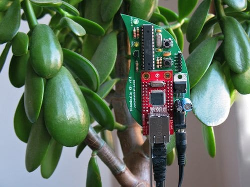
A working prototype Richard Spellman and I put together
The prototype as it fits in the casing - the pressure sensor will sit in the middle just under the acrylic tile, and LEDs and light sensors will be in each cell 
Some longer wires for the LEDs and light sensors prepared by Richard
Stephen Barrass, Natalia Lopez and Nathan Evans drilling the casing together
Also an over site - full credits for the project! Our lecturer is Stephen Barrass and the class is Vanessa Wang,  Anaer Anaer, Nathan Evans, Subyeal Pasha, Natalia Lopez, Amber Standley, Richard Spellman and myself.

Friday, April 29, 2011

D, I & E Intensive 2 Day 2

10AM

In thinking about the design approach to my tile, I have tried to establish a hierarchy of inputs and outputs to assist clarity.

The primary input I think is the pressure sensor (a footstep) as this is the direct interactive input from the audience, so output responses to this should be dominant over other outputs - and immediate. Probably all responses to inputs should be fairly immediate, else they loose legibility. So therefore responses have to either be short, additive or interruptible - rather than queued.

There are 4 neighbour communication channels (inputs/outputs). These must be treated equally I think so that the tile is robust enough to be placed anywhere. For example if a tile is placed in the bottom right corner where it has no right neighbour then it would be silly to have a response behaviour that can only be turned on with a signal from the right and equally it would be silly to try to pass output signals only to the right. Therefore  I think that all neighbour outputs should always be the same signal and that the relevant neighbour input signal states are limited to: 'I am recieveing a signal from a neighbour', 'I am recieving a signal from more than 1 neighbour', 'I am not recieving a signal from a neighbour' and 'I have not recieved a signal from a neighbour for x period of time'. In a 9 square grid - 3x3 - there is 1 centre square that has 4 neighbours, 4 squares that have 3 neighbours and 4 corner square that have 2 neighbours.

Outputs are a bit of a balancing act - between variety of responses and legibility. I could have simply on/off, which might be a bit boring (?) but very clear. At the other extreme, given that we are using analogue signals, I could have continuous gradients to give numerous variations (0-255), but these would likely be harder to distinguish. I am leaning toward steps - perhaps 3-5 to be determined by protyping (eg 3 steps would be LOW: 0-85, MID: 85-170 and HIGH: 171-255).

The output responses will be various combinations of light and sound, including varied brightness, blinking, delays, duration, and frequency, and may be thought of as calls that can be made once or perhaps repeated in a pattern.

For example:
  • Pressure LOW   >   Response 1 (OFF)
  • Pressure MID    >   Response 2
  • Pressure HIGH   >   Response 3 
  • Neighbours ALL LOW   >   Response 4 (OFF)
  • Neighbours ALL LOW for x time   >   Response 5
  • Neighbours 1 x MID   >   Response 6
  • Neighbours 1 x HIGH or 2+ x MID   >   Response 7  
  • Neighbours 1 x HIGH & 1+ x MID   >   Response 8
  • Neighbours 2+ x HIGH   >   Response 9 

That is already 9 different behaviours - at least 6 calls - perhaps even this is too much for clarity?

12PM

Stephen has suggested that as our casing has four quads that we design four pixels per tile. So visually our grid will be 9 square super cells and 36 square sub cells (6x6). We are now planning on passing out different signals on each side (regardless of whether a neighbour exists on that side) and having each pixel behave individually.

Stephen is keen that we first set up all of the tiles to behave in the same coherent way - that is is you step on a tile all four of it's pixels turn on, and then pixels in neighbouring tiles ripple on (each pixel turns on after a second delay if its neighbouring pixel is on). Each pixel has two sides (potentially two neighbours) and only recieves signals from one neighbour and only passess signals to the other neighbour (because each tile has four light sensors and four pixels) - this means that communication paths will be quite particular through the grid.

Stephen has also suggested that we dont need seperate LEDs for communication with neighbours - that leaked light from our diplay LEDs should be sufficient to register differences with the light sensors. We will prototype this and see. The great benefit of less LEDs is that is simplifies our wiring - and we only have limited breadboard space and particularly limited input/output pins on the Arduino microprocessor. We are also concerned that the little red LEDs that we are prototyping with wont be bright enough to make the display engaging - we will have to wait and see how it all comes together tomorrow. We will be able to make changes before the exhibition in Belconnen.

5PM

An update on fabrication - we collected the materials (and learnt how to tie knots to secure them to the roof of the car) and began getting the ply CNC routed in the workshop. The router doesnt cut all the way through so that pieces can be held together stably. Kudos to Nathan Evens who led documentation and supervision of the routing.

CNC router - showing different profile routs and cuts
The acrylic was already cut into 38cm squares for us by Plastic Creations and the ply came from Mitchell Building Supplies as Bunnings Warehouse doesnt keep 25mm ply in stock. We also picked up some non-slip rubber underlay from Clark Rubber.

While I had been working in the fabrication team Vanessa Wang,  Anaer AnaerSubyeal Pasha and Natalia Lopez had been leading development of the code.

12AM

This evening I was trying to tidy our code with classes but found that they dont behave the same way as in Processing and in fact need to be set up as libraries. Perhaps I can try to implement this tomorrow.

I was also experimenting with different ways to make lights fade off - for example our first code dimmed the brightness by 1 each loop (255 = on, 0 = off). A loop might take up to 15 milliseconds if there is lots of code and I didnt want to change from integers to longs - so my ideas for lengthening the fade time were to either have a counter each loop and only every nth count dim the brightness by 1 or to have a time step and only dim the brightness by 1 after each time step had passed. I went with the time step because I thought it would be more accurate.

Also I was thinking about allowing internal communication via code between the four pixels in a tile about their state (on, off etc).

Wednesday, April 27, 2011

D, I & E Intensive 2 Day 1

So begins the second intensive for Design, Interaction & Environment. The first intensive we were learning basic skills for Arduino and making some prototype critters that could sense, respond to and influence their environment. This social colony of things were able to interact with their neighbours and displayed some emergent behavior patterns. In this second intensive we are focusing on production of an installation, first for the foyer of Building 9 at the University of Canberra and then perhaps as part of an exhibition in July at the Belconnen Arts Centre.

We spent the morning discussing ideas for the installation and came to a first concept that everyone could develop an individual critter that received environmental input in different ways (laser beam broken, pressure pad in cushion, strokable grass, noise level, Theremin proximity sensor, helium balloons that pull flex sensors, Xbox Kinect movement sensor etc) but was tied together by producing a single note in a coherent soundscape in similar fashion to the ToneMatrix.

We visited the site and found that it was possible to hide things under the terrain/seat (we discovered spiders and dead mice) or behind the acoustic ceiling tiles, and that if we had things that were not too heavy we could velcro them to the green carpet roof/wall or hang them from the light fittings, but that there were not many other places we could safely attach critters. We discussed linking a visualisation on the tv screens and even broadcasting this or a camera feed voyeuristically to other tv screens around the building, and also determined that it would be possible to transmit data by the building's network and so keep our laptops if needed in the server room.

Ultimately however we decided to flip the first concept and make a unified input, as a tiled floor with pressure sensors and our critters under each tile, and have individual, divergent outputs in the form of light and sound. This will essentially be a tidier version of our social colony of things from the first intensive, with the critters still responding to neighbour states but with a more robust communication channel (better aligned, secured and calibrated LEDs and light sensors). The installation will behave and be structured much like a cellular automaton and will feel something like Dance Dance Revolution or the floor of the night club in Saturday Night Fever. As with the critters in the first intensive the light and sound outputs will probably be more of a cacophony than a symphony, but hopefully there will be coherent emergent patterns perceptible.


In the afternoon we set about designing the standard shared hardware and casings. Every tile will have the same case, the same pressure sensor, and the same neighbour communication channels (LED out, light sensor in) to ensure that they robustly fit together and can be tiled in different positions.

We visited the workshop and learnt about using the new fabrication facilities at the University of Canberra - how to set up drawings, that the CNC router can cut sheets up to 25mm deep and 1200mm wide, that routing paths can be set for inside or outside of shape edges and to any depths, and that the laser cutter can engrave by reducing the beam intensity but that depending on the material this will be to different depths.

Stephen Barrass workshopping the casing design
The casings will be 38cm square routed ply with acrylic tops. The hollowed ply will have spaces for the Arduino microprocessor, a battery (we might later try to hook up a power plug) and multiple bread boards (we want to keep the sensors and neighbour interface separate from the light and sound outputs), while maintaining structural support for the acrylic at the sides and centre.

We can get small piezo pressure sensors cheaply - they are a crystalline structure that produce a small current when pressed. The pressure sensor will be placed at the centre of the tile immediately below the acrylic where it will register even visually imperceptible bowing of the acrylic when stepped on.

We will probably use clear acrylic, meaning that individual design decisions in addition to how many LEDs to have, where to place them and how to program them also will include whether to frost or etch the acrylic or back it with translucent paper.

Tomorrow we will finalise the design of the casing and fabricate it. Hopefully we will have some time to design the content too, because the next day we plan to install!

Tuesday, April 26, 2011

Hyperbolic Coral

This post is some long overdue documentation for the Hyperbolic Coral, which was the result of a computational nature study that Kerrin Jefferis and I did for the unit 8195 Generative Design and was exhibited last November as part of Cultural Interfaces at CraftACT.

The idea of a computational nature study was to develop a generative system based on an understanding of the logic of a natural system, a practice that has been gaining momentum in architecture. In nature there are many examples of hyperbolic forms including those found in kelps, anemones and corals as well as sea slugs and leaves from lettuce to holly. Hyperbolic geometry is non-Euclidean, having at least two lines parallel to any line l through any point A not on l, and is characterised by maximised, exponentially increasing, surface area and boundary edge length. Coral needs maximised surface to collect nutrients from the sea, while sea slugs use it to propel themselves with minimal effort.

The starting point of the project was an inspiring TED lecture by Margaret Wertheim about her Crotchet Coral Reef project with the Institute for Figuring which has seen satellite reefs crocheted all around the world. We fairly literally made a digital version of this system in Processing using the Traer Physics simulation library.


Crotchet Coral and Anemone Garden with Sea Slug, Marianne Midelburg (photo: Alyssa Gorelick)

Crotchet was first used to model hyperbolic forms by Daina Taimina in 1997. Other mathematics had been struggling to model hyperbolic forms for decades. The genius of the approach is that it doesn't require a complex mathematical description of the entire form - just a simple algorithm describing the relationship between one row of stitches and the next. Normally in crotchet new rows have one stitch for each stitch in the previous row. However with hyperbolic crotchet an extra stitch is added for every nth stitch in the previous row. We have termed this a growth pattern, and conceptually thought about the coral growing from the first row.

To translate the system to Processing we needed two conceptual parts - a constructor to build relationships between stitches and a physics simulator to give material properties allowing the stitches to self optimise their position (ruffle).

Essentially the stitches are replaced with particles connected by springs. The particles are free to move and the springs can be compressed or stretched but have a rest length that they try to reach. The system comes to equilibrium when as many springs are as close as possible to their rest length - a condition that requires a resolved hyperbolic form.

The constructor takes a ring with x particles and grows i rings based on a growth pattern (eg {1,2} specifies an extra particle for every 2nd particle in the previous ring). The particles are connected by springs to the immediately adjacent particles in the ring and to the parent particle in the previous ring.

Hyperbolic Coral - {2,3} growth pattern, 4 particles in first, 5 rings 

Hyperbolic Coral - {3,3} growth pattern, 4 particles in first, 5 rings

Particle physics simulation is computationally resource intensive limiting the number of particles that a model can contain. A coarse polygon mesh makes a perceptually faceted model. We smoothed our model, approximating the form of a model with more rings of particles by exponentially increasing the rest length of springs between outer rings.

A repellent force between all particles was introduced to assist the form finding - where as fabrics have a certain stiffness this system could bend back on itself 'impossibly' and get tangled up. Additional springs could be added as cross-bracing to further reduce bending.

To ensure a stable system the strengths of all the forces including drag and spring stiffness and damping need to be continually tweaked for each change in the number and density of particles (controlled with variables such as number of particles in the first ring, growth pattern, number of rings and spring rest lengths). This constant micro management of the system doest allow a single stable profile to be set such that a 'plug and play' generic hyperbolic form generator can be sent out into the world. The version on Open Processing is stable for the range of: 5 rings; growth patterns {2,3} to {3,5}; and 4, 6 or 8 particles in the first ring.

Hyperbolic Coral - the full set of possible models from the Open Processing version
We had a go at fabricating a model using Shapeways nylon selective laser sintering (SLS). A polygon mesh was exported from Processing to Rhino where it was cleaned up, thickened into a volume 1.5mm thick and saved as an STL file for Shapeways.

Hyperbolic Coral - nylon SLS
Coral hanging out at Cultural Interfaces with Mitchell Whitelaw's Weather Bracelet and Measuring Cup
(photo: Mitchell Whitelaw)
Once released into the wild some renderings of the coral popped up at architectural scale visualising the potential for a giant pavilion! In terms of architectural application I mostly imagine continuing the exploration of self organising/optimising systems and training these for architectural purpose. A very beautiful realised installation is Chris Bosse's Green Void, which is a hyperbolic form with a different generating strategy. Of course one can also imagine functional reasons for wanting hyperbolic forms given they have exponential surface and boundary.

Hyperbolic Coral  in the wild (rendering: Dominik Raskin)
Hyperbolic Coral in the wild (rendering: Dominik Raskin)
In the future it would be nice to train the coral generator to do more tricks including accommodating different starting geometry and multiple pieces that can be stitched together. The Crotchet Coral Reef project encourages participants to introduce mutations into their algorithms to create endless variations (evolutions) that are not mathematically pure, which I suspect is a rich strategy for future exploration.

Monday, April 25, 2011

An installation that is collectively curatable

As a class project for Design, Interaction & Environment we will be building an installation for the foyer of Building 9 at the University of Canberra. The site is already perhaps the most 'designed' space at the University with a recently completed refurbishment including an astroturf seat/terrain installation opposite tv screens broadcasting news channels and many walls covered in larger than life prints of significant historical media moments.

Building 9 - two spaces, building foyer with screens and entrance to theatre beyond

Building 9 - astroturf seat/terrain

Building 9 - automatic sliding doors sense movement

Building 9 - stairs adjacent to foyer
The space presents some obvious opportunities as starting points for a new interactive layer of installation. The space is busy with people both passing through and waiting for class or to meet friends. The screens could perhaps be repurposed, the seats could become points of interaction and even the automatic sliding door already has a movement sensor. News media as an already established theme for the space, suggests rich potential additional content including social media sources such as Twitter.

However what really inspires me are projects that make intangible environmental conditions apparent in a poignant way such that a different engagement with the environment is encouraged - I highlighted this in my initial post for this unit with exemplar projects such as Scott Snibbe's Boundary Functions, Daniel Hirschmann's Tuned Stairs and Usman Haque's Sky Ear.

Equally exciting for me is that these projects can be interacted with by multiple agents. Scott Snibbe's project can only display boundaries when there is more than one person, Daniel Hirschmann's project encourages exhibitionism as people walk down stairs and Usman Haque's project visualises mobile phone calls and text messages from the audience. This idea that an installation can be curated by the audience, giving ownership and understanding of process, is powerful. Yet if the installation can facilitate collective curation, that is interactions with multiple 'authors', and be better for it (say because of shared creativity in response to emergent conditions) then it is all the more engaging.

The final important lesson is to keep it very simple. With all of these projects interaction is intuitive and feedback has distilled clarity and pertinence. Vanessa Wang has also highlighted the importance of this.    

Andre Michelle's ToneMatrix is another good project that demonstrates these principles. This week it has been emailed around the architecture studios and I have seen it cause many hours of procrastination - some students have been so fascinated that they have revisited the project a number of times. It is a web version of the Yamaha Tenori-On a synthesiser that allows you to manipulate simple sinewaves by turning on and off pixels in a matrix.

ToneMatrix, Andre Michelle, 2009
As far as proposals go for our class installation, I am interested in a sound based project that can be collectively curated. I believe that sound can cut through the existing visual clutter of the space. So how to realise an interface for a piano stair or giant physical pixel matrix synthesiser like project?

My initial google investigations found that pressure sensitive pads are expensive but that it may be possible to build our own. Vanessa Wang is proposing to work with pressure sensitive pads too. I think that that Stephen Barrass' ZiZi the Affectionate Couch used conductive thread to to make the ottoman sensitive to touch. (Clarification: Stephen says the static electricity generated by stroking the fabric was passed through the conductive thread to an input reader, essentially making the entire surface ottoman sensitive, but that this was impacted by humidity). Perhaps pressure sensitive cushions for the astroturf seat/terrain are a more achievable scale for input than mats to cover the floor, although it may be possible to make piano stairs alternatively with basic lasers aimed at light sensors such that footfalls break the beam. Subyeal Pasha proposes using lasers in a similar way. Amber Standley suggests the use of a Theremin synthesiser which neatly doesn't require any touch, producing sound in response to proximity.

A pixel matrix interface could be constructed with simple on/off buttons and basic light bulbs. It has to be at scale large enough that it can be interacted with simultaneously by multiple people. The experience would be akin to that of operating a switchboard and perhaps therefore explicitly curatorial.

When someone is not curating the installation, perhaps it could keep playing the previously curated state.
Salt Lake City Switchboard, 1914 (Image: Royce Bair)
Both Amber, with the Theremin, and Natalia Lopez, in her experiments with a magnetoPot, are pursuing a sound of (infinite) gradients. In contrast I now notice I have been thinking about a set of on/off switches. Ultimately I am comfortable with either, being more interested to see if we can establish a simple system that through local interactions can display emergent behaviours. The class already achieved this with our fireflys. Perhaps we should try to expand this and turn the foyer into a swamp inhabited by a diverse community of critters?

Vanessa goes further than the idea of curation to suggest game play as a driver of engagement. There is nothing like firing up those competitive juices for getting people hooked - here is a lovely 1994 Wired article exploring the psychology behind why Tetris is so addictive.

Anaer Anaer proposes an opposite focus, that is on mapping environmental conditions (noise).  If this is part of a larger installation then perhaps the output can be a combination of background condition and interaction, and when there is no interaction revert back to mapping background condition.

Friday, April 1, 2011

D, I & E Intensive Day 3

Today we started by getting everyone's critters working on a millis timer and then went on a field trip to the Belcconnen Jaycar electronics store. We then set up our Arduino microprocessors to be powered by 9V batteries (previously we had been powering by USB - 5V) so that they could be more portable. This required soldering a 9V battery cap to a power plug.

A team effort to solder
Ground and positive connections to plug
Battery powered portable critter
So that we didn't have to continually unplug the critter, we also set the knob to be a sound off switch - that is if it's input value was below 10 no tones were made. Finally the annoying critters were quiet! 

Then our tasks were to make our critters unique. I synchronised the LED (blink) to the tone duration, and set the light sensor to make the tone duration shorter and frequency higher in darker conditions. Finally we let our critters loose on a play date and found that some emergent patterns were discernible!

Critter play date


D, I & E Intensive Day 2

Day 2, thinking about our little circuits as fireflies and then crickets, we set out to get them to interact with each other - the building blocks for emergent behavior and swarming.

We replaced the flex sensor with a light sensor (also a variable resistor) for the input - making both the input and the output light. Now the critters could in principle talk to each other, but first we had to calibrate the values. This time we did it in a more sophisticated way - after establishing the approximate range of input values with the serial monitor, we mapped the values to the entire range of possible output values (0 to 255) to ensure maximum sensitivity. Given that counting can wrap we also constrained any input values that were outside of our approximated range to be 0 or 255.

Calibrated values printed in the serial monitor  - these are written to the output LED pin
The light sensor gives a higher value in dark conditions and so without reversing our mapping (which is as easy as swapping the toLow and toHigh values in the map function) has the effect of turning the light on when it is dark.

The second critter's light is on when the first critter's light is off
Here every second critter's light is off
We then added a buzzer (essentially a small low quality speaker - it has a disc that can be vibrated to generate different sound at different frequency), and a knob (another variable resistor - this one has 3 terminals effectively making it 2 resistors in series meaning that it doesn't need additional resistors in the circuit - 3 terminal variable resistors are called potentiometers).

The finished critter with speaker (black) at back of breadboard and blue knob at front
We experimented with using the knob and the light sensor to control the frequency and duration of the tone. At first the sound was continuous because of the speed of the loop - another tone would begin immediately. We added delays, as we had previously with the blinking light. However delays pause the entire program, including the light sensor, making it all rather clunky!

I decided to use the time since the program had been running (called with the millis function) to set up intervals - I have used a similar strategy previously in Processing. That is: if the time now is greater than the time that the previous tone began plus the previous tone duration plus the interval then begin the next tone.

Timer using If statements and millis()

D, I & E Intensive Day 1

Today we learnt about Arduino and basic electrical circuits. Arduino is an open-source electronics prototyping platform centred around a microprocessor that is controlled by uploaded code. The microprocessor can be stand-alone or can interact with software running on a computer.  The development environment is based on Processing, which is also open-source. As with Processing, Arduino has a large community of users including many artists and visual designers.

I have already been using Processing and am excited to take projects beyond the computer. So the point of Arduino is that the microprocessor facilitates interaction with the environment including human interfaces beyond the screen, keyboard and mouse. Inputs can be considered environmental sensors that measure things like sound, light, heat, movement. A very cute example is Rob Faludi's Botanicalls that measures soil moisture and sends tweets to remind you to water your plants and then once you have sends another tweet thanking you.

Botanicalls, Rob Faludi and SparkFun
Outputs can include sound, lights and motorised movement and are often understood to respond to the environmental sensors, although it is not necessary to use dynamic/interactive inputs and outputs at the same time.

We started with a tutorial by Lady Ada to upload code to the microprocessor that caused a LED to blink. This apparently is the hardware equivalent of a hello world.

Arduino microprocessor with simple circuit (blinking LED)
We setup our circuit on a breadboard which has rows of already connected pins that make it easy to 'plug and play'. It consists of a light emitting diode (LED), a resister for safety and wires for signal and ground connected to the Arduino microprocessor. The ground wire is connected to the ground pin (marked GND) and the signal wire is connected to a digital pin, which can only give high voltage or low voltage (ground or 0) - that is on/off.

The colour of cables is used to organise the circuit with clarity - we are using black for ground and red for high voltage (apparently these are conventions), and then green and orange for variable signals as input and output respectively.

Resistors are important to restrict the current, both to ensure that fragile parts such as the diode dont get fried and to reduce the risk of electrocution. I am not yet totally across when to use resistors and how much resistance to choose - I suppose it always somewhat necessary to check specification of parts. Lady Ada  suggests that a 100 ohm resistor is sufficient to protect a diode and that generally a 1000 ohm  (1K ohm) resistor is a good place to start. The relationship between current, resistance, and voltage is described by Ohm's Law: Current (I) = Voltage (V) / Resistance (R). The level of resistance is notated with coloured bands.

The way we controlled the blink is with simple code that in the loop function (equivalent to the draw function in Processing) says light on (high voltage signal), then delay (pause the program, light remains on), light off (low voltage signal) and then delay again (pause the program, light remains off).

We also learnt about drawing circuit diagrams, as you can see in the background of the above picture.

The next project was to reconfigure the circuit to make the LED dim-able. We added a flex sensor as an input - it is a variable resistor that changes input signal (voltage drop) as it is bent. The input and output signal had to be connected to an analog pin on the Arduino microprocessor. The analog pins (marked ~ ) can use pulse width modulation (PWM) to vary voltage - how this actually works is that the duty cycle or the amount of time that is high or low each clock cycle can be set between 0 (always low) and 255 for output or 1023 for input (always high) effectively turning on/off so quickly that it is imperceptible and appears as continuous and smooth. As there are different ranges for the input and output values it is necessary to calibrate - in this case we offset the input value to be below 255.

LED dimmed using flex sensor as input

Design, Interaction & Environment

This is the first of a series of blogs for the unit Design, Interaction & Environment which can be followed with the tag 8200 (the unit number). This unit is being led by Stephen Barrass who has many exciting projects in this field and a particular focus on data sonification (making sound from data). We will be using Arduino and experimenting with inputs from environmental sensors, human interfaces and other data sources, and outputs that have a physical manifestation in the environment such as light, sound and movement. Ultimately as a class we will make an installation for the foyer of Building 9 at the University of Canberra. It is nice to be reassured by Tom Igoe that there is merit in doing another iteration of a theme already well established.

My initial interests in interactivity and environmental awareness stem from a cursory look at some of the following projects as I have come across them, with little understanding of the systems behind them or in general what physical computing is about.


Automation - are buildings too complex for users?

The first and obvious architectural application of physical computing is automation of building systems in response to environmental stimuli - for example adjusting the position of shading or photo voltaic panels based on sun position, turning on/off lights based on occupancy and levels of daylight, adjusting ventilation (opening/closing windows) and turning on/off mechanical heating and cooling systems based on temperature. These computerised controls are broadly referred to as Building Management Systems (BMS) and are often largely unnoticed by building occupants.

The mantra with sustainable buildings, particularly solar passive houses, is that they need active users - windows, curtains etc must be opened/closed at correct times and if they are not, the building can perform significantly worse than a conventional building! Automated systems are common in new commercial buildings and perhaps for this reason could also be important in houses.

A visually expressive example of an automated system is Jean Nouvel's Arab World Institute brise soleil which is a beautiful array of 240 motorised apertures evoking traditional Islamic screens.

Arab World Institute, Paris, architect Jean Nouvel, 1981-87 - the brise soleil seen from interior
A more contemporary example on a larger scale is LAVA's solar umbrellas for the plaza in their winning Masdar City Center design. The solar umbrellas are modeled on flowers and fold up at night.

Masdar City Center design competition winning entry, LAVA, 2009 - solar umbrellas in public plaza


Making the intangible tangible

The next projects are interactive art installations. I, like Vanessa Wang, keep coming back to Scott Snibbe's Boundary Functions. I first saw this project when I was experimenting with abstracted Voronoi diagrams to arrange program and divide space in a second year architecture studio led by Iain Maxwell.

Boundary Functions, Scott Snibbe, 1998
Boundary Functions uses a Voronoi diagram to project personal space as cells with boundaries halfway between people and their neighbours - that is that all space within in the cell is closer to the owner than their neighbour. The cell size, shape and boundary change dynamically as people move and population densities vary. The system uses an overhead camera and projector to track people and display the diagram. I like this project because it makes an important environmental condition that is usually experienced by feeling tangible in a visual way that allows it to be better understood. Personal space is not often thought about critically and this installation makes apparent the contextual nature of it - that is that personal space is not fixed and can only exist in relationship to your neighbours. Snibbe further comments that as the installation can only exist with more than one person and in a physical space, it is a reversal of the usual lonely self-reflection of virtual reality or frustration of virtual communities.

On questioning personal space, this time in relation to machine (can you be intimate with a machine?), I also very much liked a student project that Bert Bongers showed at the 2007 AASA Conference. It was an installation (creature) that had long stick-like limbs and picking up movement or proximity would lean over to be near you (is it leering at me or is friendly? is it invading my personal space? is it going to touch me?!)

Tuned Stair, Daniel Hirschmann 2006, Fabrica exhibition, Centre Pompidou
Another favourite is Daniel Hirschmann's Tuned Stairs - part of the 2006 Fabrica exhibition at the Centre Pompidou. These piano stairs have pressure sensitive pads (mat switches) installed on stairs that (through an Arduino microprocessor!) each trigger a different note. This is a very simple and beautiful  way to make legible the different cadences of people as they move through the space - it also encourages people to perform. Grand stairs in theatres particularly, where patrons are dressed up, but all stairs in public places to some extent, are already associated with performance or exhibitionism. The piano stairs are a contemporary interpretation of giving tuned resonances to architectural elements - an idea that has been resolved by Carlo Scarpa as musical steps in the Brion Cemetery and by Vijayanagara temple builders as musical columns that the priests 'play' most famously in the Vittala temple.

Musical Stairs at Brion Cemetery, Carlo Scarpa 1970-72
Vittala Temple, Vijayanagara 15C
The other project in this theme that I really like, again for it's simplicity, is Usman Haque's Sky Ear which is a floating sculpture of helium balloons, electromagnetic sensors and mobile phones. The changing colours of the balloon LEDs make apparent the underlying electromagnetic patterns and the impact of calls and messages to the balloon phones.

Sky Ear, Usman Haque 2004, Greenwich
Dan Hill in his narrative The Street as Platform further elaborates an understanding of digital substrates - layers of data that can be collected, made legible and interacted with.


The beginnings of a physical computing syntax

From reading a couple of background papers presented at the Sketching in Hardware 2010 conference a syntax, or taxonomy even, for interaction design begins to emerge.

Carla Diana talked about a natural user interface, exemplified by the the gestures used to control the iPhone's touch screen. Emphasising appropriate gestures, screen readability and ergonomics, Diana discussed the position of metaphor, abstraction, mapping, feedback, delight and personality in interface design.

Ellen Do elaborated on this theme,  calling for a human centric view of designing interactions for example

  • Hand: touch, press, pick up, hold, squeeze, gesture 
  • Body: sight, sound, sense, sit, stand, walk, sleep, movement pattern
  • Environment: light, space, ambiance, navigation, context aware.

Do describes a responsive architecture as an environment that takes an active role, initiated changes as a result and function of complex or simple computations, but also knows me and the context it is in and establishes a framework of considerations for designing A-E-I-O-U:
  • Activities: What are they doing?
  • Environments: Where is it taking place? (eg location, noise, lighting, all the senses)
  • Interactions: With whom are they interfacing? (eg talking, seeing, collaborating)
  • Objects: What are they using? (eg chair, projector, keyboard)
  • User: Who are they? (eg group, individuals, roles, demographic data)


One final project that I want to mention is the interactive white board style hacks for projectors and flat screens using Wii Remotes to track the position of a pen that has an infrared LED. In 2009 Leo Carson and Christine Murray led a group of other MDD students, with support from Mitchell Whitelaw and Gurdev Singh to successfully implement a version in Processing. They ended up setting Boon Jin Goh's Smoothboard, a program that already has more sophisticated features built in, for design crits in the architecture studios. On screen markups that can be recorded as stills or movies finally brings to digital presentations the immediacy and intuition of traditional iterative feedback processes using butter paper. You can see in the video below Gurdev enjoying marking up my project.